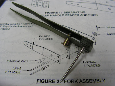
Step 1: Separate the Flap Handle Fork and Flap Handle Spacer.

Step 2: Make the Fork Assembly using the Flap Handle Forks, Spacers and hardware called out on page 32-07 of the RV-12 aircraft planes.
Step 3: Cut the Flap Handle Tube to length.

Step 4: Carefully align the Fork Assembly with the Flap Handle Tube, clamp the parts together, then match-drill #30 the two holes in both side of the Fork Assembly into the flap handle tube.


Step 6: Separate the Flap Detent Bracket Angle and the Flap Dentent / Stop into individual parts.
Step 7: Attach the Flap Dentent Bracket Angles to the Flap Detent Bracket.

Step 8: Cleco the Flap Detent Angle that has the holes in its horizontal flange to the Flap Detent Bracket Plate.
Step 9: Match-drill #30 the holes of the Flap Detent Bracket Plate into the Flap Detent Angle that has no holes in its horizontal flange.

Step 10: Machine countersink the bottom of the Flap Detent Bracket Plate for the flush rivets.

Step 11: Attach the Flap Detent Bracket Angles to the Flap Detent Bracket to the Flap Detent Bracket Plate using the rivets called out.
Builder's Note: Before attaching the bracket I polished it with aluminum polish rather than painting it.


This completes most of page 32-07 and this entry on the RV-12 airplane. The only thing left is the final installation of the Flap Knob in the Flap Handle.
Reference page 32-08.
Step 1: Insert the Flap Detent Bracket through the slots in the Flap Handle and between the Flap Handle Forks.
Step 2: Make temporary 0.025 inch shims from scrap aluminum and place them between the Dent Bracket Assembly and the Seat Floors, then screw the Assembly to the seat floors.
Held off on step 3, 4 and 5 until the paint dries a little longer. As it is still soft.
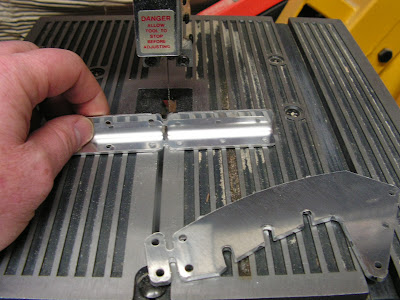
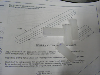
Step 6: Cut the Spacer into four individual parts according to the dimension given on page 32-08 of the RV-12 plans.
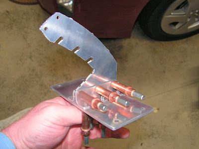
Step 7: Position the Spacers in the Flaperon Torque Tubes, then match-drill #30 the holes of the flaperon torque tube into the spacers.

Step 8: Final drill #12 the two holes in each Spacer (the spacers only, not the flaperon torque tubes).
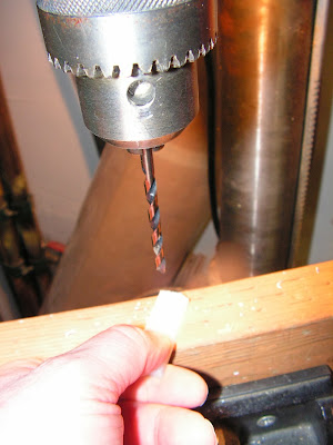
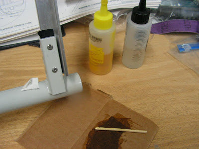
Step 9: Scuff the mating surface, then epoxy the Spacers to the Flaperon Torque tubes. Do not use too much epoxy, a 1/8 inch gap must be maintained between the spacers (use a scrap piece of 1/8 aluminum). Before the epoxy sets, install the rivets called out.
Builder's note: I cleaned to contact area on the torque tubes and spacers with MEK before gluing them with epoxy.
That completes this blog entry. Until next time.

