If working with a plan revision wasn't enough there is also this Service Bulletin to install in the RV12s fuel tank during it construction. I do have to admit I'd much rather do it now than after the fuel tank was installed! So for full disclosure, I will list all of the steps and add a big "NA" by the ones that don't apply in my case of construction.
Step 1: NA Drain all fuel from the aircraft.
Step 2: NA Remove the fuel sender wire from the Fuel Tank Assembly. Remove the fuel tank assembly from the aircraft.
Step 3: NA Remove the T-1209 Sender Plate from the Fuel Tank Assembly. See Page 37- 04, Figure 3. Clean the cured sealant from the mating surfaces of the sender plate and the T-1202 Fwd Tank Bulkhead.
Step 4: NA Drill-off the two K1000-3 Nutplates that are attached to the aft side of the T-1205 Fwd Tank Bracket. See page 37-02, Revision 1, Figure 3.
Step 5: NA Position the T-00008 Inboard Clip and T-00009 Outboard Clip against the T- 1201 Main Tank Skin as shown on Page 37-02, Revision 2, Figure 3. Mark the head of the rivet attaching the main tank skin to the T-1202 Fwd Tank Bulkhead that must be removed in order to allow installation of the T-00008 Inboard Clip. Mark the heads of the two rivets attaching the main tank skin to the T-1202 Fwd Tank Bulkhead that must be removed in order to allow installation of the T-00009 Outboard Clip. Drill-out the three rivets that were just marked.
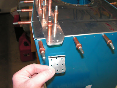
Step 6: Cleco the T-00008 Inboard Clip and the T-00009 Outboard Clip to the aft side of the T-1205 Fwd Tank Bracket and to the T-1201 Main Tank Skin as shown in Page 37- 02, Revision 2, Figure 3. Match-Drill #30 the main tank skin using the holes in the inboard and outboard clips as templates.

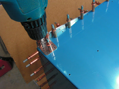
Uncleco the inboard and outboard clips and deburr the newly drilled holes. Prime and/or paint the inboard and outboard clips if/as desired.
NOTE: Read Section 5S for more information on fuel tank sealant. The tank is assembled much like any other structure with two important differences: Apply sealant between scuffed and cleaned parts that comprise a seam through which fuel could conceivably leak. This includes every fastener. Spin fastener shanks in sealant to apply a thin even coating before they are inserted. Read through this section and scuff mating parts before beginning assembly. Set rivets slowly using a hand blind rivet puller, allowing the tank sealant to displace before the rivet is completely set.
Step 7:Completed during normal construction Rivet the T-00008 Inboard Clip and T-00009 Outboard Clip to the T-1201 Main Tank Skin as shown on Page 37-02, Revision 2, Figure 3. Coat the shop heads of the inboard and outboard clip rivets with fuel tank sealant.
Step 8:Completed during normal construction Rivet one of the nutplates removed per step 4 above to the T-1205 Fwd Tank Bracket and T-00008 Inboard Clip as shown in Page 37-02, Revision 2, Figure 3. Rivet the second nutplate removed per step 4 above to the fwd tank bracket and T- 00009 Outboard Clip as shown in Page 37-02, Revision 2, Figure 3.
Step 9:Completed during normal construction Check to be thoroughly sure that no chips or construction debris remain in the Fuel Tank Assembly.
Step 10: Will be completed during normal construction Re-install the T-1209 Sender Plate with fuel tank sealant using the hardware called out on Page 37-04, Figure 3. Use a 1/16 inch thick layer of sealant between the sender plate and the T-1202 Fwd Tank Bulkhead and in place of the IE F-385 Gasket. Tighten screws just enough to cause sealant to bulge evenly from underneath the perimeter of the sender plate. Step 11: Re-install the Fuel Tank Assembly as shown on Page 37-06, Revision 2, Figure 1 and Page 37-07, Figure 3.
CAUTION: BOLT-00002 torque should be standard AN value 20-25inlb, plus the prevailing nutplate torque (usually <10inlb). Torque in excess of this may shear the frangible head.
Re-install the Fuel Sender Wire as shown on Page 37-08, Figure 1.
Step 12: To Be completed as soon as I get a aircraft log book! Make an entry in the aircraft logbook indicating that this Safety Bulletin has been complied with.
CAUTION: The tank sealant must be fully cured before refueling the aircraft for return to service.
That all for this fuel tank service bulletin. One thing I am doing is I have a three ring binder devoted to Service Bulletin. In it I keep a copy of each bulletin and documentation. Next I will continue with fuel tank construction for the RV12 airplane.

