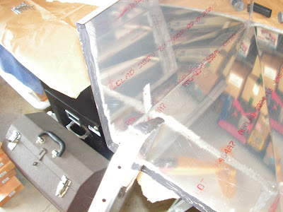
This entry starts the assembly of the fuel tank for the RV-12 E-LSA aircraft made by Van's Aircraft. There has been a revision in the plans that includes an extra set of mounting reinforcements and a simplified assembly of the filler neck fitting on the tank. Because my kit was produced before the revision I find myself working with two sets of plans. As I work through this I will do my best to outline which is which.
NOTE: Throughout this section prime any parts if/as desired except any area that will be inside the tank. NOTE: Read Section 5S for more information on fuel tank sealant. The tank is assembled much like any other structure with two important differences: Apply sealant between scuffed and cleaned parts that comprise a seam through which fuel could conceivably leak. This includes every fastener. Spin fastener shanks in sealant to apply a thin even coating before they are inserted. Read through this section and scuff mating parts before beginning assembly. Set rivets slowly using a hand blind rivet puller, allowing the tank sealant to displace before the rivet is completely set.
Step 1: Machine countersink the T-407 Ring nutplate attach holes.
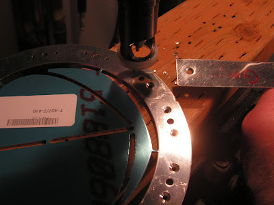
Step 2: Remove and discard the area shown in Figure 1 hatched from the T-407 Ring.
 Step 3: Adjust the joggled ends of the T-1202 Fwd Tank Bulkhead top flange to be parallel to the rest the top flange as shown in Figure 2 on page 37-02 of the RV12 plans.
NOTE: The flanges of the T-1202 Fwd Tank Bulkhead are bent toward the aft face of the part.

Step 4: Dimple the T-1202 Fwd Tank Bulkhead, flush on the forward side, at the nutplate attach holes.

Step 5: Rivet the nutplates, T-407 Ring and T-1202 Fwd Tank Bulkhead together as shown in Figure 2. Refer to the fwd tank bulkhead and ring as the Fwd Bulkhead Assembly.

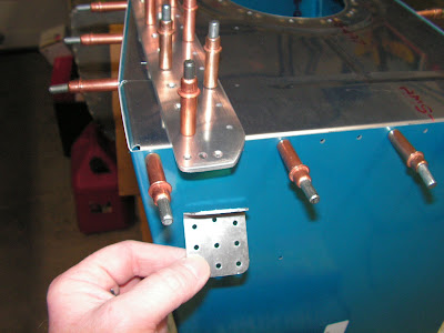
Step 6: Machine countersink the #40 holes on the forward side of the T-1205 Fwd Tank Bracket for the rivets called out in Figure 3 and deburr.

Step 7: Machine countersink the lower row and right two top #30 holes on the forward side of the T-1205 Fwd Tank Bracket for the rivets called out in Figure 3. Deburr the edges of the fwd tank bracket.

The next two steps are from Service Bulletin 11-12-14.
Reference: SB 11-12-14; Step 5: Position the T-00008 Inboard Clip and T-00009 Outboard Clip against the T- 1201 Main Tank Skin as shown on Page 37-02, Revision 2, Figure 3.Mark the head of the rivet attaching the main tank skin to the T-1202 Fwd Tank Bulkhead that must be removed in order to allow installation of the T-00008 Inboard Clip.Mark the heads of the two rivets attaching the main tank skin to the T-1202 Fwd Tank Bulkhead that must be removed in order to allow installation of the T-00009 Outboard Clip. Drill-out the three rivets that were just marked.Builder's Note: There are no rivets to drill out because this is new construction.
Reference: SB 11-12-14; Step 6: Cleco the T-00008 Inboard Clip and the T-00009 Outboard Clip to the aft side of the T-1205 Fwd Tank Bracket and to the T-1201 Main Tank Skin as shown in Page 37- 02, Revision 2, Figure 3. Match-Drill #30 the main tank skin using the holes in the inboard and outboard clips as templates. Uncleco the inboard and outboard clips and deburr the newly drilled holes.

Reference page 37-02
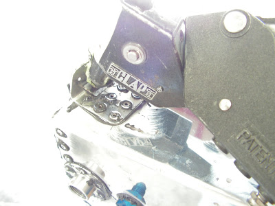
Below is a picture of my way of metering the fuel tank sealant components.

Step 8: Rivet the VA-210 Fuel Flange and the T-1201 Main Tank Skin to the Fwd Bulkhead Assembly per call-outs in Figure 3 of the RV12 plans.
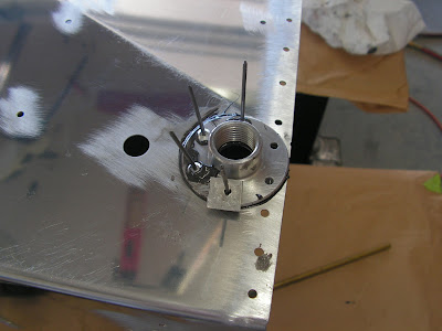

Step 9: Install the AN832-4D bulkhead fitting to the T-1201 Main Tank Skin per call-outs in Figure 3.
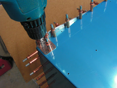
Step 10: Rivet the T-1205 Fwd Tank Bracket to the Fwd Bulkhead Assembly using rivets called out in Figure 3.
Step 11: Rivet the T-00008 Inboard Clip and T-00009 Outboard Clip to the T-1201 Main Tank Skin as shown in Figure 3.
Coat the shop heads of the inboard and outboard clip rivets with fuel tank sealant
Step 12: Rivet a nutplate to the T-1205 Fwd Tank Bracket and T-00008 Inboard Clip as shown in Figure 3.
Rivet a second nutplate to the fwd tank bracket and T-00009 Outboard Clip as shown in Figure 3.

NOTE: When installing fluid fittings with pipe threads do not use Teflon Tape! Use instead fuel lube or equivalent pipe thread sealing paste
Step 13: After the sealant cures, install the VA-261 Fuel Strainer as shown in Figure 3.
This completes page 37-02 of the construction of the RV12 aircraft fuel tank.

