This is the third and final entry on installing the fuel in the fuselage of the RV-12 aircraft kitted by Van's Aircraft. I have to say leaving the attachment of the RV12's tailcone until later has worked out very well when it comes to installing the fuel lines in the airplane fuselage.
Step 1: Attach the bulkhead fitting called out in Figure 1 to the F-1204D Center Section Bulkhead.

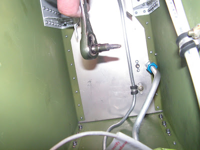
Builder's note: In the picture above you can see how the washer is modified to fit the lip in the bulkhead. In the picture below are the wrenches I used to Tighten the bulk head fitting. It is a two person job to install correctly.


Step 2: Make the Fuel Return Line Aft by unrolling and cutting 37.5" of 1/4" aluminum tubing. Start at the tank end of the tube. Insert a nut and sleeve over the end of the tube and then flare the end.

Step 3: Using the dimensions given in the side view on Page 28-07 bend the F-1259H Fuel Return Line Aft.
Step 4: Add a bend to the Fuel return Line Aft after it passes by the left side of the Fuel Pump to transition to the bulkhead fitting in the Center Section Bulkhead. Slip a sleeve and nut over the forward end of the return line then flare the end. Attach the return line to the bulkhead fitting.

Step 5: Make six F-1259K Pads by cutting lengths of EA HOSE H175 hose 3/4" long and then slit them lengthwise. Place these around both the F-1259F Fuel Line Tank - Pump and F-1259H Return Line as shown in the detail view in figure 1 of the RV-12 plans. At three locations clamp around both pieces of hoses as shown by Van's Aircraft in figure 1 on page 28-06.


Step 6: Make the F-1259M Fuel Return Line Fwd by unrolling and cutting off 71.25" of 1/4" aluminum tubing. Start at the forward end of the tube. Insert a nut and sleeve over the end of the tube and then flare the end.

Step 7: Measure back 14 1/4" from the forward end of the F-1259M fuel Return Line and mark a start of bend line. Make a 90 degree bend towards the clamp on the firewall shown in Figure 1 of the RV-12 airplane planes. Make the remaining bends as required to position the return line in the clamp on the firewall as well as aligning the top of the line with the return line hole in the Firewall Shelf. The distance on the completed return line to the lower face of the firewall shelf should match the dimensions given in the Detail View in Figure 1 .


Step 8: Feed the Fuel Return Line through snap bushings to the bulkhead fitting on the Center Section Bulkhead. Lay the tube into the left most recess for a tube in the System Blocks adding a slight curve to follow the curvature of the Bottom Skin.
Step 9: Slide the Fuel return Line Aft while curving it with your hands to exit the fuselage bottom through the center bottom access hole.
Step 10: Insert a nut and sleeve over the end of the Fuel Return Line and flare the end. Re-straighten the curve formed in Step 9 as the fuel return line is slid forward to its installed position. Attach the fuel line to the bulkhead fitting.

Step 11: Attach the union bulkhead fitting to the Firewall Shelf per callouts in Figure 1 on page 28-06 of the RV-12 airplane plans. Attach the Fuel Return Line to the union bulkhead fitting.

This completes page 28-06 of the RV-12 plans and section 28. After this I vacuum tested the complete system with good results (no Leaks.)

