So today start the Cooling system for the RV-12 in ernest.
NOTE: Save excess EA HOSE H151 material for use in Section 50.
Step 1: Cut two lengths of EA HOSE H151 per the dimensions given in Figure 1 on page 49-02 to make the FF-1208A Radiator Hose - Input and FF-1208B Radiator Hose - Output.
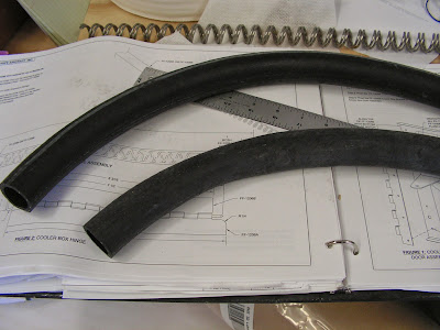
Step 2: Deburr the ends of the FF-1208C Expansion Springs.

Step 3: Insert a FF-1208C Expansion Spring inside of the FF-1208A Radiator Hose - Input and FF-1208B Radiator Hose - Output in the location called out in Figure 1. Grab the end of the spring with pliers and twist spring to reduce its outside diameter if necessary.
Builder's note: The spring that shorter of the two hoses appears to be longer than the hose. Not sure why if it becomes an issue I will document it in an upcoming blog entry.

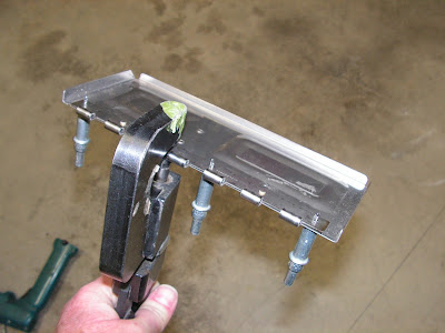
Step 4: Make the FF-1206A and FF-1206B Cooler Box Hinges from MS20257C4-4 Stainless Steel Hinge using the dimensions given in Figure 2 in the RV 12 plans page 49-02.
Step 5: Make the FF-1206C Hinge Pin from SSP-120 Stainless Steel Hinge Pin.

This completes page 49-02.
Reference: 49-03
Step 1: Align the FF-1206B Cooler Box Hinge with the FF-1205 Cooler Box Door as shown in Figure 1. Match-Drill #40 the holes in the cooler box door into the cooler box hinge. Cleco as you drill.

Step 2: Disassemble the FF-1206B Cooler Box Hinge from the FF-1205 Cooler Box Door. Deburr the cooler box hinge.
Step 3: Dimple all the #40 holes in the FF-1205 Cooler Box Door per the rivet call-outs in Figure 1.

Step 4: Machine countersink the #40 holes in the FF-1206B Cooler Box Hinge and FF-1205B Cooler Box Bracket for the dimples in the FF-1205 Cooler Box Door.

Step 5: Rivet the FF-1206B Cooler Box Hinge to the FF-1205 Cooler Box Door.
Step 6: Rivet the FF-1205B Cooler Box Bracket to the FF-1205 Cooler Box Door per the call-outs in Figure 1. This will complete the Cooler Box Door Assembly.

Step 7: Align then clamp in place the FF-1206A Cooler Box Hinge with the FF-1204A Cooler Box Face as shown in Figure 2. Match-Drill #30 the holes in the cooler box face into the cooler box hinge. Cleco as you drill.
Step 8: Disassemble the FF-1206A Cooler Box Hinge from the FF-1204A Cooler Box Face. Deburr the cooler box hinge.
This completes page 49-03 and this entry in the RV-12 airplane build blog.

