Today will just about finish up the wing wiring for the RV-12 airplane lights.
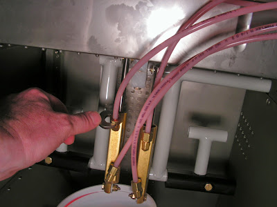
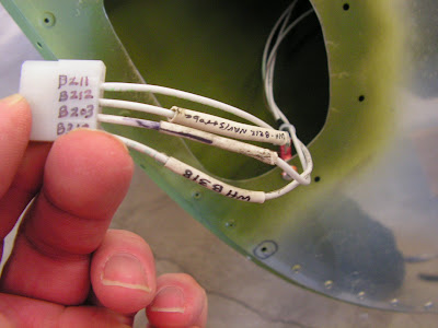
Step 8: Snap the female Molex pins on the ends of the WH-B211 (WHT) Nav/Strobe Ground Wire and WH-B212 (WHT) Nav Power Wire, WH-B203 (WHT) Strobe Power Wire, and the WH-B318 (WHT) Strobe Synch Wire into a male Molex connector housing in each wing tip.
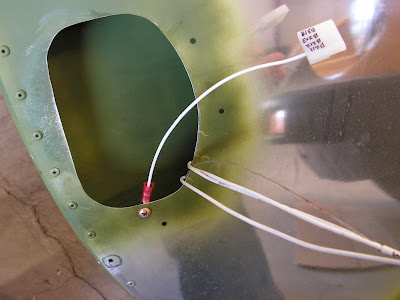
Step 9: Tie-Wrap all four wires together near the ring terminal on each wing tip to prevent the wires from rubbing on the edge of the access opening.
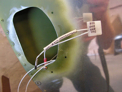
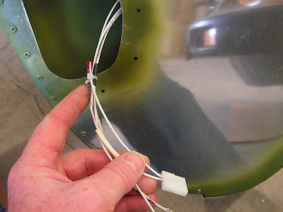
Step 13: Label the Molex connector housings as to which wire goes in what position.
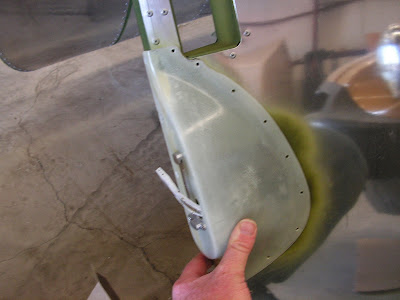
That's it for today's work . Next I will start in on the prep for painting and finishing of RV-12 including the fiberglass parts. I have decided to paint the plane myself using Epibond epoxy primer and Aerothane for the top coat. Because this is a time consuming task with not much interest points for separate entries I will do one mass blog entry explaining the process and how long it took. So until then enjoy! I will also be doing an entry on how to register an ELSA aircraft between now and then as well.