Reference: Servcie Bulletin 12-11-09 and SB 12-09-26; ~12hours
Steps 1-7 are for RV12s that are finished or at least more completed than mine.
Step 8: Support the aircraft using sawhorses, so gear is off the ground. Builder's note: The gear are not yet installed so I simple supported it on my build table with the fuselage sitting on its side.

Steps 9-11: Again these steps did not apply to my partially completed RV12, because the brakes and landing gear are not installed.
Step 12: Use a Step-Drill to drill 3/8" holes in the bottom Skin to allow for insertion of a drift (for seating the bolt hardware). See figure 2 of Service Bulletin 12-11-09 page 4 of 30. This will permit torque to be applied to the head of the U-1202 attach bolts.

Steps 13 amd 14: Deals with removing the landing gear and cutting/removal the wing root seal so these are not applicable to my partially completed RV12 airplane.
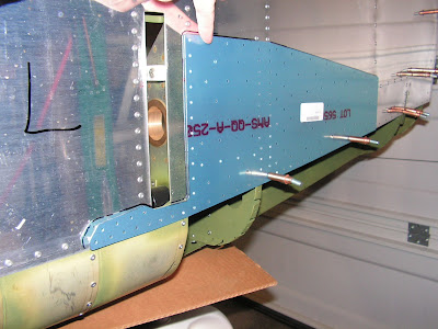
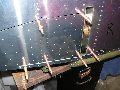
Step 15: Mark a zone on the side of the fuselage using the F-1270A Doubler as a guide for rivet removal. Remove all rivets that have callouts depicted in Figure 6 on page 7 of 30 of the service bulletin from Van's Aircraft.

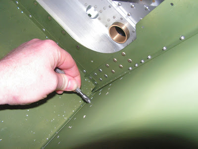
Builder's Note: The steps I use are pictured below. Basically these are drive the rivet stem out with a small punch; drill the head with an 1/8" drill (just through the head not the hole); pop the head off with a tappered 1/8" punch; tap the rivet tail out using a backing block.


Steps 16-17: Deal with paint ridges but is not applicable in my case as the RV12 is not painted.
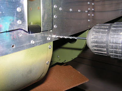
Step 18: Carefully remove the rivets holding the F-1204T-L & -R Skin Stiffeners to the F-1204 Center Section Assembly . At these eight rivets location, it is acceptable to use 12" long #30 extension drill to access the rivets from below, through the gear leg opening in the fuselage side. See Construction Manual Page 20-40.


Step 19: Not applicable to a new fuselage. But is very important for flying RV12s as it is looking for damage! In the Service Bulletin from Van's Aircraft are example pictures of possible damage.
Step 20: Remove the blue vinyl plastic from the Side Skin Doublers, and cleco them to the sides of the fuselage.
NOTE: Before doing any drilling, confirm that all wiring, carpet, upholstered side panels ( and anything else) are moved away from the fuselage side skins so it doesn't get damaged while drilling.
Step 21: Match-Drill #30, all holes in the Side Doublers into the Fuselage Side Skin, etc. where holes in the aircraft structure do not already exist.

Builder's Note: Because of the RV-12 not being completed, I found I need to install the bottom fuselage edge piece for drilling as well.
Step 22: Machine countersink all of the rivet locations in the Side Skin Doublers shere CS4-4 rivets will be installed. Use a 120 degree cutter with a #30 pilot. Cut these just deep enough for a flush fit of the rivet. See Figure 6 on 7 of 30 of Van's Aircraft SB 12-11-09.

Step 23: Separate the F-1204U-B left & right and F-1204T-2 left & right from each other by cutting.

Step 24: Bend a slight upward angle on the flange extensions on the bottom flange forward and aft edges of the F-1204U-B angles.
Step 25: Cleco the F-1202U-B angles into position (cleco all holes.) Use a 12" #30 drill and match drill from below up through the four holes in the F-1204 Center Section (cleco each hole as you drill.)

Step 26: Uncleco and remove the F-1204U angles, and deburr the holes match drilled in the previous step.
Step 27: Remove the side skin doublers and deburr all accessible holes in the fuselage side skins that were match drilled.
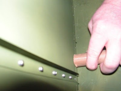
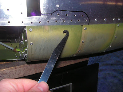
Builder's Note: Pictured below is a Chip Chaser which is helpfull during this step
Step 28: Deburr the edges of the Side Skin doublers. Prime the doublers.
Step 29: use a shop vacuum to remove all rivet tails, drill shavings from interior areas of the fuselage.

Step 30: Tap the Spar pin Bushing in the Center Section fwd slightly to improve access to the fwd most rivet that attached the F-1204U and F-1204T Angles.
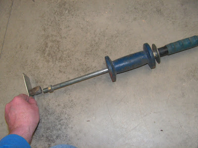
Builder's note: I used a body side hammer with a protected flat plate to drive the bushing forward.
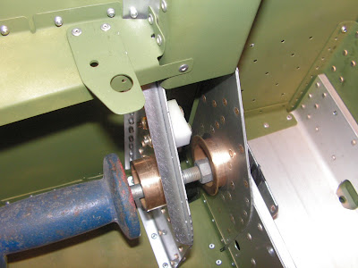
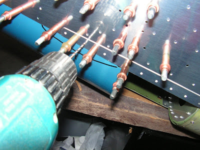
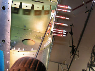
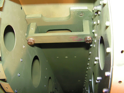
Rivet the Angles to the Center Section Assembly using CR3213-4-5 rivets. Press the Spar Pin bushings back into their original position.

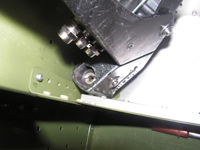
Builder's note: In the picture below the Cherry Max rivet on the right did not pull correctly. The stem was driven out, the head removed and the rivet replaced. In my case this was due to not pulling the rivet perfectly straight up because of the rivet puller head clearance.

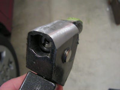
Builder's note: I had to modify the head to fit into the corners then everything worked fine. Anyway make sure the rivets don't "pop" prematurely or they will have to be drilled out!
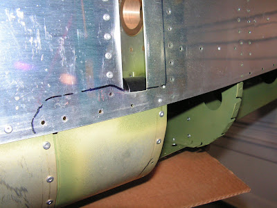
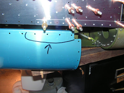
Step 31: Rivet the Side Skin Doublers to the fuselage structure using the rivets called out in the service bulletin.

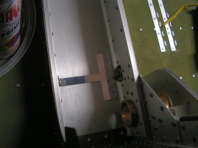
Builder's note: When I tried pulling the Cherry Max rivet with a pneumatic rivet setter some of them lifted up. See rivet with arrow pointing to it in picture below. So I finish pulling these with a hand puller. End up removing the few that were not seated correctly.

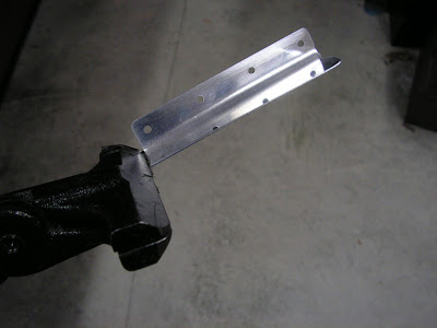
Step 32: Add bevels to the four corners of the Outboard Main Gear Attach Brackets as detailed in RV-12 SB 12-09-2. Builder's note:I ended up taking these to work and using a milling machine to do the work.
NOTE: The following Steps are repeated on both the right and left side of the aircraft.
WARNING: Since the parts and the drill template are not symmetrical, be very sure you have them properly oriented (new holes being added are beside the forward bolt.)
Step 33: NA. Deals with inspection for cracks.
Step 34: Deburr the edges of the Outboard Doubler Plates and the Outboard Wear Plates.
Step 35: Remove the blue vinyl plastic from both sides of the Drill Template.
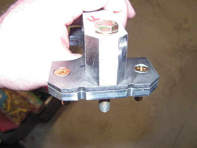
Step 36: Attach the Drill Template to the top side of the Center Section Assembly with the Outboard the Outboard Main Gear Attach Bracket, Outboard Doubler Plate and Waer Plate to the lower side of the center section assembly at the attachment location for the main gear lages. Note that the stell wear plate goes below the doubler plate. Use old AN365-524 nuts and washers under the head of the bolts as required to pull the assembly up tight.
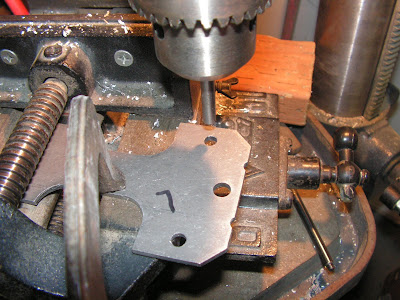
Step 37: match-Drill #30 the two.125 holes called out in Figure 17, through all parts using the template as a drill guide. Use the reflection of the drill in the template to check that the drill is perpendicular to the surface of the template.

Remove the template leaving the remaining parts still attached to the center section assembly and repeat this step for the left side of the aircraft, except leave the template in place after drilling the holes. on the left side. Install new double sided tape as necessary.
Step 38: Using the reflection visible in the template to keep the drill bit perpendicular to the surface, drill 1/4" both holes just match-drilled #30. Remove the template and all of the other associated parts, taking note of their orientation they were in when drilled.

Mark the doubler and Wear Plate that will allow re-installation of them in the same position as when drilled.
Step 39 Relocate the template back to the right side. Re-Tighten the hardware holding the attach bracket, doubler and wear plate, and drill template in place. The template is being re-installed for it's reflective properties. Repeat the drilling process from the previous step for the two holes on the right side.
Remove the template and all other parts. Mark these as to orientation just as done on the left side.
Step 40: Deburr the 1/4" holes in the Center Section, Outboard Doubler Plates and Outboard Wear Plates.
Step 41: Clean all drill shavings from plane.
Step 42: Machine countersink the lower side of the Outboard Wear Plate at two locations drilled in the previous step for the head of the AN509-416R17 Screws supplied with the update kit. Be sure to countersink the bottom surface of the Outboard Wear Plate.
Use a 100 degree machine countersink too. See the Service Bulletin for details on countersinking these bolt holes and use cutting oil during the process. The outside diameter of aproper depth countersink is 1/2".


Step 43: Lightly prime (keep primer thickness to a minimum) the Outboard Doubler Plates, Outboard Wear Plate, Inboard Wear Plate and Inboard Doubler Plates.
To prevent rust, lightly coat the gear leg where it contacts the Wear Plates with grease.
Step 44: Priming and painting of Side Skin Doublers. I will do this at the same time the rest of the RV-12 is painted.
Step 45: Install the Outboard Doubler Plate and Wear Plate to the Center Section Assembly as shown in Figure 20 of Van's Aircraft Service Bulletin instructions. USe 2 temporary AN5 bolts as alignment pins to assure alignment while torquing the nuts on the screws.
BUILDER'S NOTE: Van's has a good discussion of torque values on page 23 of 30 of the Service Bulletin.

Steps 46 - 62: Each of these steps will be completed as the Rv-12 is completed.
This was a long entry, but an important one. As I mentioned it's not really a step by step guide but rather my experiences with completing Service Bulletin 12-11-09 for the RV-12 aircraft. Next time I will start in on building the fuel tank for the RV12. Till then be safe.

