Vans Aircraft RV-12 Build, Section 21: Mid Fuse Bibs & Bottom Skins (part 4)
Reference: page 21-04, 21-05, 39-02; 11.0 hours
A couple of things before I get started. First I am planning on installing the autopilot option, so this is the time to start in on section 39 Autopilot Servo Brackets. Some of the steps from each of the two sections are intermixed. Second the parts need to install the servo brackets are included with the fuselage kit in a separate bag.
Step 1: Separate the F-1219 Flaperon Mixer Arm by removing the hatched area shown in Figure 1 on page 21-04 of the RV-12 plans.
 Step 2:
 Rivet the two F-1218 Flaperon Mixer Brackets to the F-1202A Forward Intercostal and the F-1220B Aft Intercostal.
 Step 3:
 Machine countersink the nutplate attach rivet holes in the Flaperon Mixer Arm, then attach the nutplates called out in Figure 2 of the RV-12 plans.

,br/>
 Step 4:
 Bolt the F-1219A & B Flaperon Mixer Arms and the bushings called out in Figure 2 to the F-1218 Flaperon Mixer Brackets using the hardware shown by Van's Aircraft on page 21-04 of the RV-12 plans. Torque the bolt enough to remove any slop or play, but still allow freedom of rotation.
Builder's note: The bushings are in hardware bag 2715. Also it is not called out in the plan but I lubricated the bushings and washers parts with Areoshell #5 grease.
 Step 5:
 Bolt the second, longer bushing called out in Figure 2 between the F-1291A & B Flaperon Mixer Arms.
 Step 6:
Separate the four Seat Belt Attach Lugs, and the two F-1216 Seat Belt Attach Lug Supports.

 Step 7:
 Remove the vertical strip of material from the lightening hole of each F-1215-L&R Seat Rib as indicated in Figure 6 of ther RV-12 plans on page 21-04.
 Step 8:
 Using F-1215-L&R Seat Ribs, Seat Belt Attach Lugs, and Seat Belt Attach Lug Supports, cleco together four Seat Rib Assemblies; two right and two left.
 Step 9:
 final-Drill #30 the eight 1/8" dia. holes common to all the parts , then rivet them together.
 Builder's note: This completes page 21-04.
Reference page 21-5
Step 1:
 Set aside two Seat Rib Assemblies (one left and one right). In the remaiining two Seat Rib Assemblies, final-drill #19 the screw holes for the nine nutplates depicted in Figure 1 on page 21-05 of the RV-12 plans. Note that in the case of the MS21051-L08 nutplate, the screw hole is NOT the center hole.
 Step 2:
 Dimple the indicated attach hole for the MS21051-L08 nutplate in the aft, sloped flange of the two Seat Rib Assemblies. (The second attach hole has been factory dimpled.)
Step 3: Dimple the four K1000-08 nutplates called out in Figure 1, then rivet them to both Seat Rib Assemblies. The five remaining nutplates are installed on paers 21-07 and 21-08.

Step 4: In both Seat Rib Assemblies, dimple (flush on top) the three #30 holes.

Builder's note:some of the pictures show the parts before priming and then after priming. A few of these steps I did out of sequence so I could prime them all at once.
Step 5: Locate the four remaining Seat Ribs. In all four seat ribs, final drill #19 the screw holes for the nutplates depicted in Figure 2 of the plans.
Reference 39-02 Step 1: Trim the called out F-1215 Seat Rib by removing the material shown hatched in figure 1 on page 39-02.
Builder's note: It is easy to get the seat ribs mixed up so go slow double check before cutting!!!


Reference 21-05 Step 6: Set aside one pair of the Seat Ribs (one left and one right). Dimple the nutplates shown in Figure 2, then rivet them to the remaining two Seat Ribs.

Step 7: Dimple the nutplates shown in Figure 3 on page 21-05 of the RV-12 plans and the corresponding holes in the Left Seat Rib Assembly(the left seat rib assembly from Figure 1), then rivet the nutplates in place.


Builder's note; My Flaperon Stops were curved and needed to be straightened see picture below.

Step 8: Machine countersink the two holes, indicated in Figure 3, in both F-1252 Flaperon Stops.These are 120 degree counter sinks NOT the standard 100 degree!

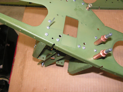
Step 9: Rivet one of the F-1252 Flaperon Stops and the Pulley Bracket Assembly to the left Seat Rib Assembly using the rivets called out in Figure 3.

Step 10: Rivet the F-1215-L Seat Rib that has the nutplates installed from step 5 to the Pulley Bracket Assembly as shown in Figure 3.

Step 11: Dimple the nutplates shown in Figure 4 and the corresponding holes in the Right Seat Rib Assembly (the right seat assembly from Figure 1 on page 21-05.

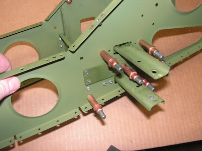
Step 12: Rivet the remaining F-1252 Flaperon Stop and the Flaperon Mixer Arm Assembly to the Right Seat Rib Assembly.
Reference 39-02; Step 3: (Step 2 is NA) Cleco the F-1269 Servo Doubler to the F-1215-R Seat Rib as shown in Figure 2. Match-Drill the holes from the servo doubler into the seat rib per the call-out in Figure 2, Detail A-A.

Reference 39-02; Step 4: Rivet the Servo Doubler to the F-1215 Seat Rib per the call-out in Figure 2. Detail A-A.

Reference 39-02; Step 5: Rivet the F-1269 Servo Doubler to the F-1220B Aft Intercostal. See Figure 1 for assembly orientation and Figure 2 for rivet call-out.


Reference 39-02; Step 6: Install the screw, washer and nut called out in Figure 2. Rotate, then rivet the nutplate back into place using the rivet called out in Figure 2.

This completes page 39-02.
Reference 21-05 Step 13: Rivet the F-1215-R Seat Rib that has the nut plates installed from Step 5 to the Flaperon Mixer Arm Assembly.


