Wednesday, June 29, 2011

Vans Aircraft RV-12 Build, Section 16: Stall Warning (part 2)

Reference: page 16-03, 16-04; 2.5 hours

Today's work will finish the installation of the Stall Warning assembly in the RV-12 aircraft wing. SOme of the pictures include a few of the electrical wiring tools I own and use. Most came from SteinAir. A link to their website is in the link section of this blog.They are also the manufactures of many of the wiring harness used by Van's Aircraft for the RV-12. Also, they are great people to work with.

Step 1: Make the WH-B217 (WHT) Ground Wire by cutting #18 gauge wire 5 inches long and installing an ES DV18-188-M female spade connector on one end of the wire and an ES 31890 on the other. Double check that the connectors are properly installed!


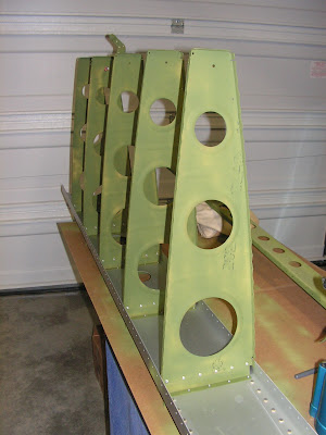
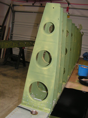
Step 2: Install the Stall Warning Sub-assembly on the W-1208-R Nose Rib. The upper screw goes through the slot in the VA-195A Mount and allows the angle of the Stall Warning Sub-assembly to be adjusted. The lower screw passes through the ES 31890 terminal on the WH-B217 (WHT) Ground wire.


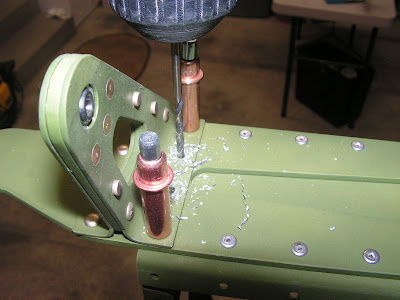
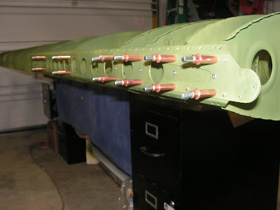
Step 3: Carefully position the W-1202-L Mid Skin over the W-1208-R Nose Ribs and Stall Warning Sub-assembly and cleco.


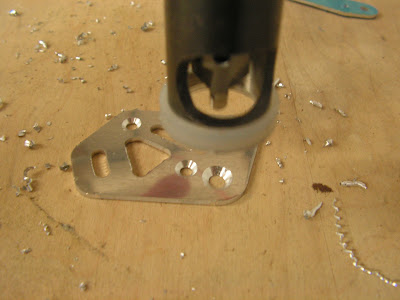
Step 4: Double check that the VA-196 Stall Warning Vane in the "at rest" position is perpendicular to the surface of the wing skin. If the stall warning vane is not perpendicular, remove the Stall Warning Sub-assembly and bend the stall warning vane as required. See figure 3 on page 16-03 of plans. Adjust the sub-assembly until the VA-196 Stall Warning Vane activates and deactivates the ES E22-50K Micro Switch with the minimum travel possible (it is permissible to bend the arm on the micro switch if/as needed.)


Step 5: Remove the clecos and W-1202-L Mid Wing Skin.

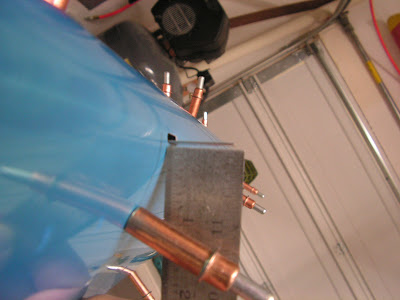
Step 6: Make the WH-B218(WHT) Terminal Wire by cutting #18 gauge wire 68 inches long. Install an ES DV18-188M female spade connector on one end of the wire. Double check that the spade connector is properly installed.


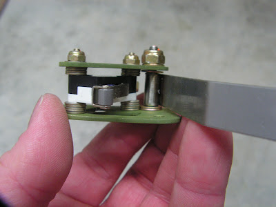
Step 7: Install the WH-B218 (WHT) Terminal Wire to the N.O. (normally open) terminal of the ES E22-50K Micro Switch as shown in Figure 1 on page 16-03. Start at the stall warning sub-assembly, route the terminal wire inboard through the snap bushing in each W-1208 Nose Rib headed inboard. Install the WH-B217 (Wht) Ground Wire to the COM. (common) terminal of the ES E22-50K Micro Switch.


This completes page 16-03.

Reference page 16-04

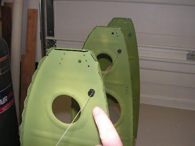
Step 1: Cut two 12 foot lengths of string or fishing line.

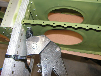
Step 2: Starting from the most outboard W12-08 nose Rib, route a length of string inboard through the snap bushings in all of the nose ribs. Tape the ends of the string on the outboard and most inboard nose ribs. Repeat process on the right wing.


Step 3: Take the inboard end of the WH-B218 (WHT) terminal Wire and attach a ring connector. Ensure that the connector is properly installed.


Step 4: Make two WH-B216 (WHT) terminal Ground wires by cutting #18 wire to 5" lengths and attaching a ring connector to each end.


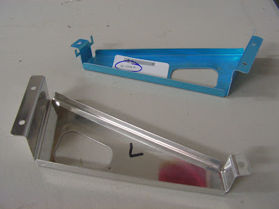
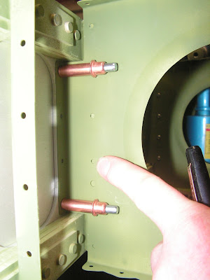
Step5: Attach the WH-B218(WHT) Terminal Wire and one of the WH-B216 (WHT) Terminal Ground Wires to the W-1205-L Terminal Brackets.


Step 6: Attach the second WH-B216 (WHT) Terminal Ground Wire to the W-1205-R Terminal Bracket.


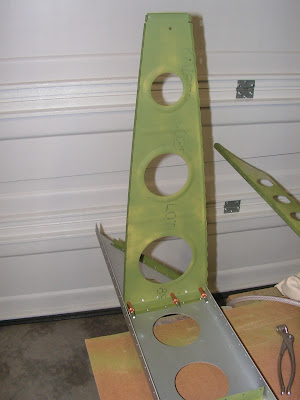
Step 7: Install the W-1205-L and _R Terminal Brackets. Take care not to pinch wires between the attachment point. Route the WH-B216 (WHT) Terminal Ground Wires around the forward flange of the terminal brackets and fasten the connector with the terminal bracket mounting screw. other wires should be neatly tucked behind terminal bracket.

Builder's note: For this last step I only temporarily fit the brackets as they will by remove during the next section because I am installing the lighting kit. Second, i like to use Noalox Anti-Oxidant Compound for wires grounded against aluminum. It is designed to help the electrical connection so corrosion doesn't form and give electrical problem down the line. It's made by Idea Products and is available from HomeDepot in the electrical section.

This completes section 16. Next will be Section 17, skinning the wings.

Monday, June 27, 2011

Vans Aircraft RV-12 Build, Section 16: Stall Warning (Part 1)

Reference: page 16-02; 2 hours

It's time to start a new section on the RV-12 airplane kit by Van's Aircraft. This section deals with installing the Stall Warning vane/switch in the wing. Also I will discuss the "fun with washers" on the Stall Warning Assembly.

Step 1: Final-drill #30 the holes in the VA-195A Mount Plate and VA-195B Keeper Plate that are used to mount the ES E22-50K Micro Switch. Machine countersink both holes of the mount plates inboard side for the flush head of the #4 screw.


Step 2: Final-Drill #19 the hole in the VA-195A Mount Plate and VA-195B Keeper Plate that holds the #8 screw on which the VA-196 Stall Warning Vane pivots. Machine countersink this hole in the mount plate on the inboard side for the flush head of a #8 screw.


Step3: Deburr all holes and edges.


Step 4: Assemble the Stall Warning Subassembly. Do not over-torque the nut on the screw about which the VA-196 Stall Warning Vane pivots. Insure that the stall warning vane can rotate freely.

Builders note: Fun With Washers. There are three different NAS washers called out on page 16-02, however the washers supplied use the older AN- number. Because of this, crossreferencing can be interesting. So here are the equivalents: NAS1149FN416P = AN960-4L; NAS1149FN432P = AN960-4; NAS1149FN832P = AN960-8.


Step 5: Take the W-1205-L and W-1205-R Terminal Brackets and remove the bending tabs. Deburr all holes and edges.


Step 6: Clamp the PS UHMW .125X2X2 1/4 to the W-1205B/F-1270C Guide UHMW Drill Template, match-drill #40 all holes, clecoes may be added to keep part from turning. Final drill to create the W-1205B Terminal block. Repeat for the second terminal block. Save the drill template for use during Section 31.


Step 7: Place the W-1205B Terminal Block on the outboard side of the W-1205-L Terminal Bracket and rivet. Repeat process for W-1205-R Terminal bracket.

Tuesday, June 21, 2011

Vans Aircraft RV-12 Build, Section 15: Wing Ribs (part 9)

Reference: page 15-05; 2 hours

The left main spar is now back from Van's Aircraft and ready to go. First the rib assemblies were re-riveted to the spar. While the work is being noted here I am not photo documenting the process because I don't want to confuse anyone as it is not part of the normal construction process. So that leave us where we stopped on page 15-05 starting with Step 3.

Step 3: Select four of the forward trimmed W-1208-R Nose Ribs and cleco then rivet to the W-1206-L Spar Assembly and attach angles.


Step 4: Cleco then rivet the forward trimmed W-1208-L Nose Rib to the W-1206-L Spar Assembly and attach angle.


Step 5: Cleco then rivet the forward and aft trimmed W-1208-R Nose Rib with the attached nutplates to the attach angle.


Step 6: Cleco then rivet the Left Stub Spar Assembly to the forward flanges of the W-1208-L and W-1208-R Nose Ribs.


Step 7: Insert the SB375-4 snap bushings into the W-1208 Nose Ribs.


This completes page 15-05, Section 15 and the wing frames. Next will be the installation of the stall warning vane.

Monday, June 13, 2011

Vans Aircraft RV-12 Build, Section 15: Wing Ribs (part 8)

Reference: page 15-06, page 15-07; 1.5 hours

This entry continues the assembly of the right wing frame of the RV-12 aircraft.

Step 8: Cleco the Right Rear Spar Assembly to the flanges of the W-1210 Main Ribs.


Step 9: Match-drill #30 the hole locations in the aft flange of the main rib. Remove clecos and Rear Spar Assembly and debar the match-drilled holes as required.


Step 10: Take the Right Rear Spar Assembly and cleco then rivet to the aft flanges of the W-1210 Main Ribs.

Builder's note: LP 4-4 rivets are used for the four holes in the picture below. Also the main ribs with the flaperon hinges attachments use the inboard set of rivet holes to mount the ribs.


This completes page 15-06.

Reference page 15-07

Note: With the bottom of the W-1210 Main Ribs resting on the work surface, a weight or clamp may be applied to the aft position of the wing assembly to hold it in position for attaching the W-1208 Nose Ribs. Take care not to bend the flanges of the W-1210 Main Ribs.

Step 1: Cleco then rivet the eight remaining aft trimmed W-1208-L Nose Ribs to the W-1206-R Spar Assembly attach angles, starting out board and working inboard.


Step 2: Select the four forward and aft trimmed W-1208-L Nose Rbis (no attached nutplates) and cleco then rivet to the W-1206-R Spar Assembly attach angles.


Step 3: Cleco then rivet the forward and aft trimmed W-1208-R Nose Rib to the W-1206-R Spar Assembly attach angles.


Step 4: Select the forward and aft trimmed W-1208-L Noes Rib with attached nutplates and cleco then rivet to the W-1206-R Spar Assembly attach angles.


Step 5: Cleco then rivet the Right Stub Spar Assembly to t
he forward flanges of the W-1208-L and W-1208-R Nose Ribs.


Step 6: Insert the snap bushings in the W-1208 Nose Ribs.


This completes page 15-07 and the frame of the right wing. Next time I will double back and complete the left wing.

Saturday, June 11, 2011

Vans Aircraft RV-12 Build, Section 15: Wing Ribs (part 7)

Reference: page 15-05, 15-06; 5 hour

In this entry I ran into a major snag on the RV-12's left wing! While attaching the nose ribs to the left main spar, the 3rd and 4th ribs (from the inboard end) didn't fit the predrilled attachment angle holes (see picture below.) These two angles had been transposed during fabrication of the spar. Van's Aircraft was very helpful and after much discussion the final solution was to remove the rib assemblies (only took 90 minutes) and take the spar back to Van's for the angles to be removed and reattached. I will add this to the Gotcha list, however I think this just a one-up event.


Builder's Note: The picture below is of the repaired left spar. These attach angles can easily be inspected by laying a straight edge along them.


Builders note: Other possible Gotcha's: First, LP4-4 rivets must be used in when riveting the ribs directly to the main spar (pictures below.) This is noted next to one of the drawing but not directly in the instructions. Second, when riveting the ribs to the attach angles the factory head should be on the rib not the attach angle.


Enough fun and gotcha's! Lets cover what went well.

Reference page 15-05

With the bottom of the W-1210 Main Ribs resting on the work surface, a weight or clamp may be applied to the aft position of the wing assembly to hold it in position for attaching the W-1208 Nose Ribs. Take care not to bend the flanges of the W-1210 Main Ribs.

Step 1:
Select five of the aft trimmed W-1208-R Nose Ribs and cleco then rivet to the W-1206-L Spar Assembly attach angles starting outboard and working inboard. Rivets should be installed with the manufactured head on the nose rib.


NOTE: LP4-3 rivets should be installed with the manufactured head on the rib(not on the attach angle). Use LP4-4 rivets to attach the W-1208 Nose Ribs aft flange to the W-1206-L Spar Assembly.

Step 2: Select two unmodified W-1208-R Nose Ribs, as well as the untrimmed nose rib that has the two nutplates to the spar assembly and attach angle. Cleco then rivet the last of the unmodified nose ribs to the spar assembly and attach angle.


Builders Note: Because of the challenge with the left spar I jumped over completing steps 3 through 7 and went on the the right wing.

Reference page 15-06:

Step 1: Lay the W-1206R Spar Assembly on the work surface with the flange facing up. Select one of the forward trimmed W-1210-L Main Ribs and cleco then rivet to the furthest outboard attach angle on the spar assembly.


Step 2: Cleco then rivet the forward trimmed W-1210-L Main rib which was match-drilled to the W-1216B-R Hinge Rib to the next inboard attach angle on the W-1206-R Spar Assembly.


Step 3: Select three of the forward trimmed W-1210-L Main RIbs and cleco then rivet to the next inboard attach angles on the W-1206-R.


NOTE: Use LP4-3 for attaching W-1210 Main Ribs to spar attachment angles. Use LP4-4 for attaching W-1210 Main Ribs to W-1206-R Main Spar Assembly


Step 4: Select one unmodified W-1210-L Main Rib and cleco then rivet to the next inboard attach angle and to the W-1206-R Assembly.


Step 5: Cleco then rivet the W-1210-L Main Rib which was natch-drilled to the W-1216B-R to the next inboard attach angle and to the W-1206-R Spar Assembly.


Step 6: Cleco then rivet the remaingin five W-1210-L Main Ribs to the next inboard attach angles and to the W-1206-R Spar Assembly.


Step 7: Cleco then rivet the forward trimmed W-1210-R Main Rib with the attached W-1210B-R RIb Doubler to the most inboard attach angle on the W-1206-R Spar Assembly.


That end this installment of the RV-12 aircraft build. Stay tuned as we cover more wind assembly on the E-LSA aircraft.

Tuesday, June 7, 2011

Vans Aircraft RV-12 Build, Section 15: Wing Ribs (part 6)

Reference: page 15-04; 1 hour

Step 5: Select five more of the W-1210-R Main Ribs and cleco then rivet to the next inboard attach angles on the Spar Assembly.


Step 6: Cleco then rivet the W-1210-L Main Rib with the attached W-1210B-L Rib Doubler to the remaining attach angle on the Left Spar Assembly.


Step 7: Cleco the Left Rear Spar Assembly to the aft flanges of the W-1210 Main Ribs.


Step 8: Match-drill #30 the hole locations in the flange of the main rib. Remove the clecos and the left Spar Assembly and deburr the match-drilled holes.


Step 9: Cleco then rivet the Left Rear Spar Assembly to the aft flanges of the W-1210 Main Ribs.


Builders note LP-4-4 must be used on these four holes in the picture above!


Builders note: For the two ribs with the flaperon hinge use the inboard holes to mount the ribs, as pictured above.